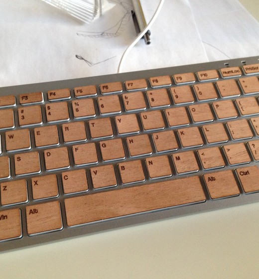
Mahogany Keyboard Cover
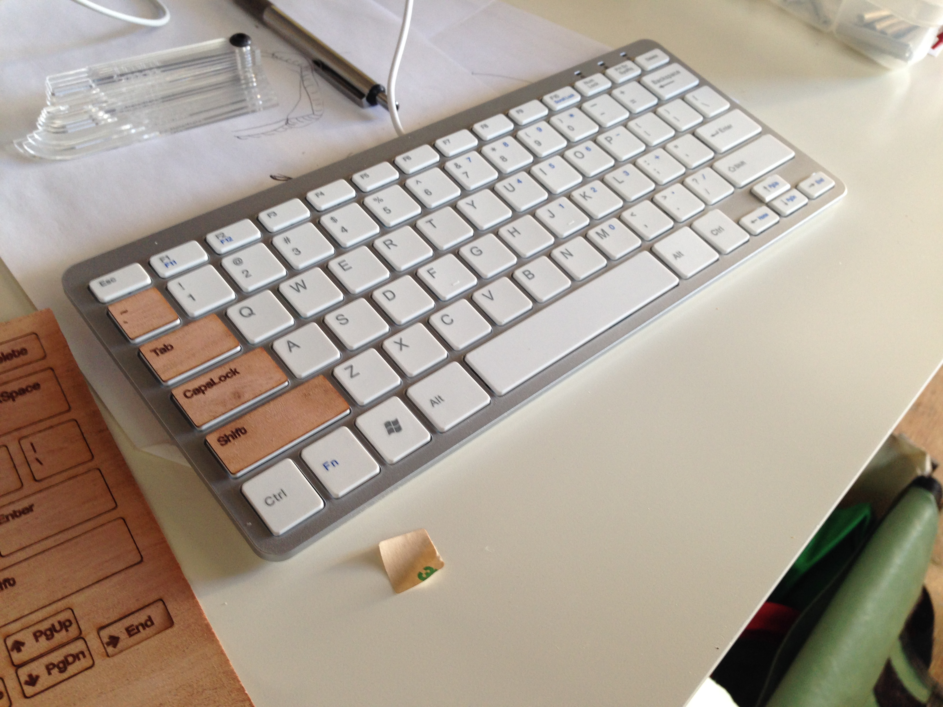
So this was a quick project I thought would be fun late on a friday. The premise here is simple: take some wood veneer and cutout key covers for a usb keyboard we had around to give it a nice wood finish look. There are a few examples out there for macbook keyboards that I’ve seen (I think there was a kickstarter for one recently). The keyboard we had in house is VERY similar to the Apple wireless keyboard, though seems like they changed it just enough to avoid a lawsuit (it was built for PC use). Anyway, I had to model up this keyboard for an unrelated project and figured it would be an easy/fun project to take a dxf off of that print and cutout the keys. The key to this is mostly in getting a good model of the keyboard. Obviously, key spacing isn’t as important here but the key size is. The other important part is getting the kerf of your machine correct (which I missed on a bit).
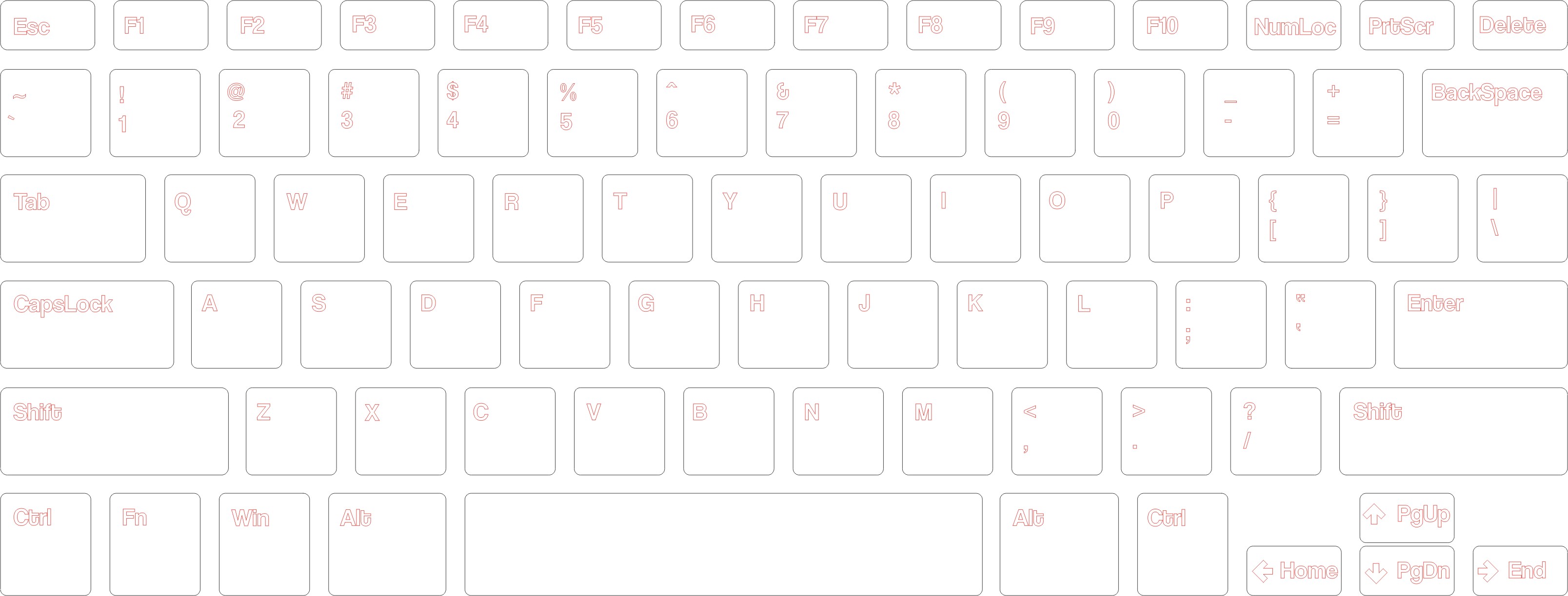
Now for materials and setup, I used some PSA-backed Mahogany veneer that I had picked up from Rockler some time ago. This provides a good adhesive for sticking to the keys and makes layout a lot easier. In terms of putting this together I was working quickly and wanted to see how well this came out without any additional finishing steps to the wood. I was wrong about that bit, and will certainly use some type of finish when I make one of these again. So I’ve got my model of the keys in solidworks (or whichever cad you’re comfortable with) and before exporting I offset each of the key outlines by half of the kerf on my machine. Again, make sure you get this right with some test cuts. I overcompensated on mine and the wood was a bit too large for the keys. The dxf that I had exported looks like this: [gview file=”http://motimindustries.com/wp-content/uploads/2013/10/keyboard.dxf” profile=”4″ save=”1″]
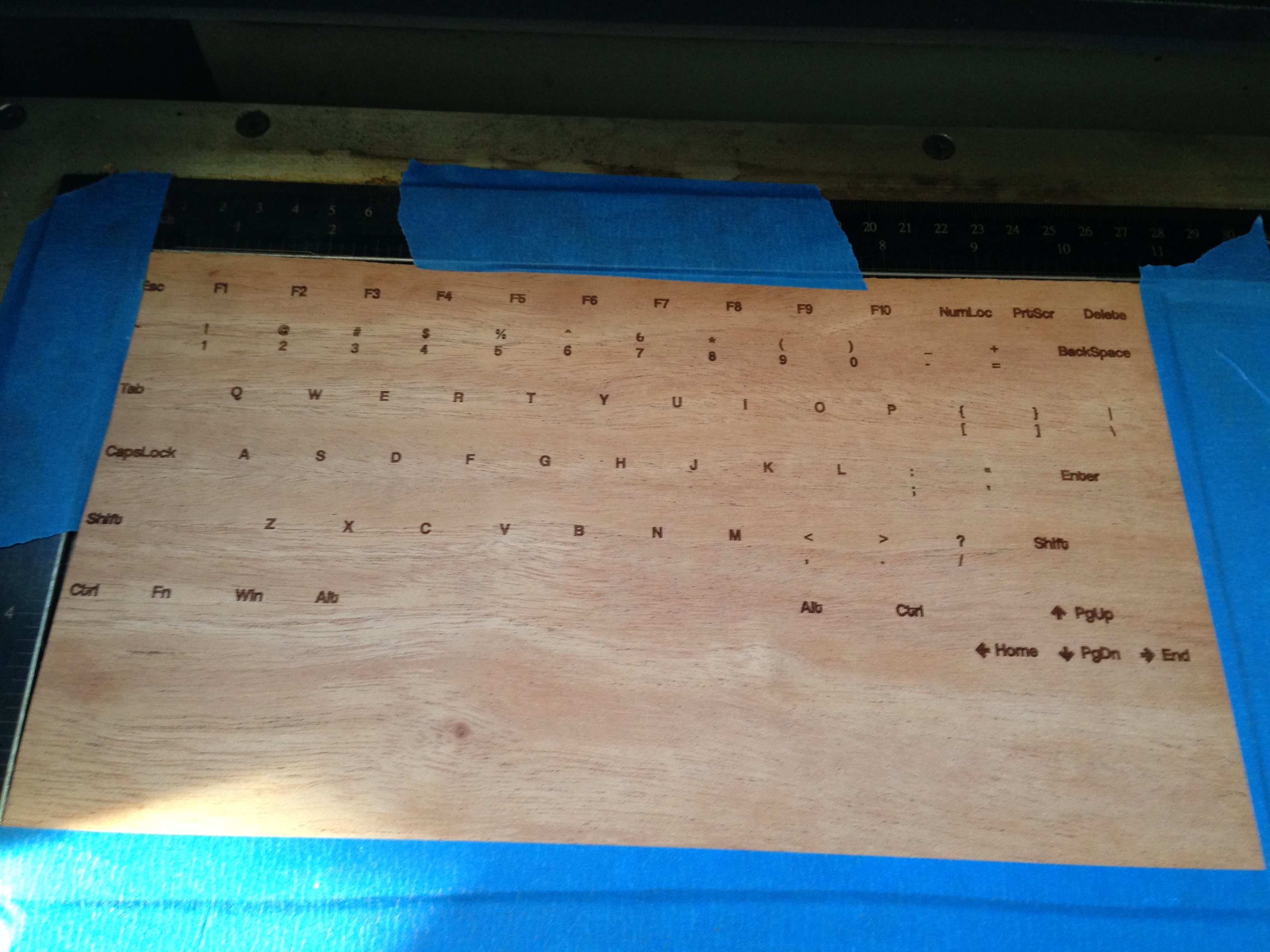
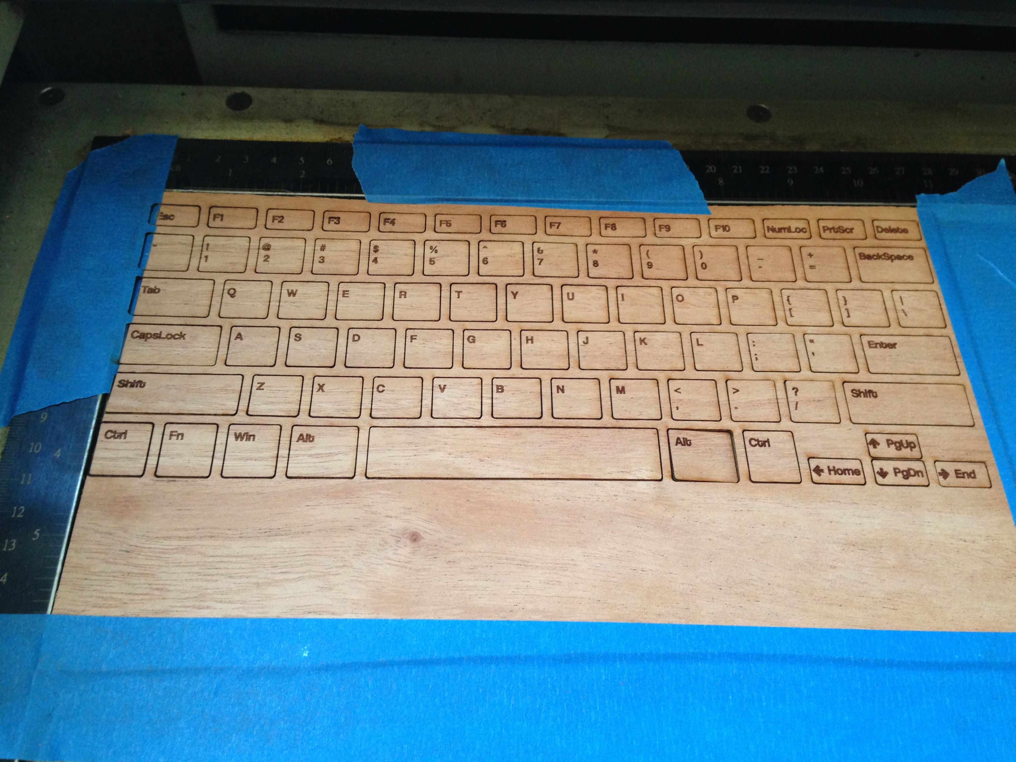
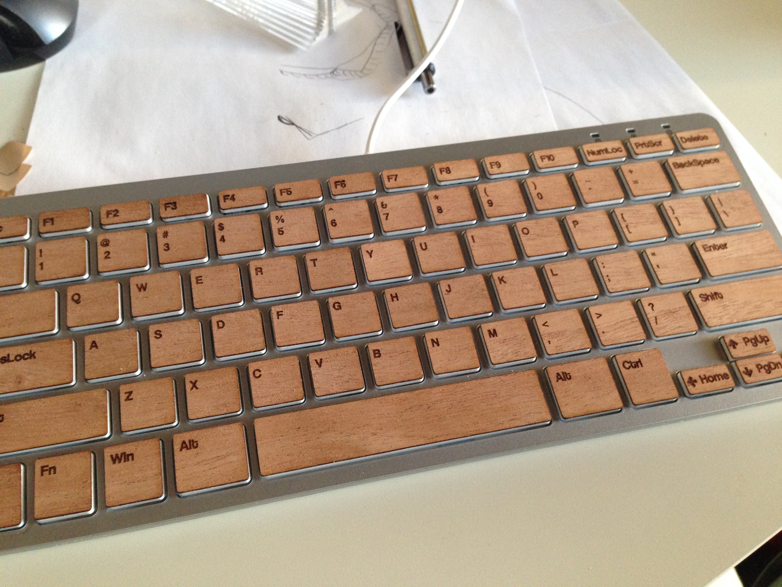
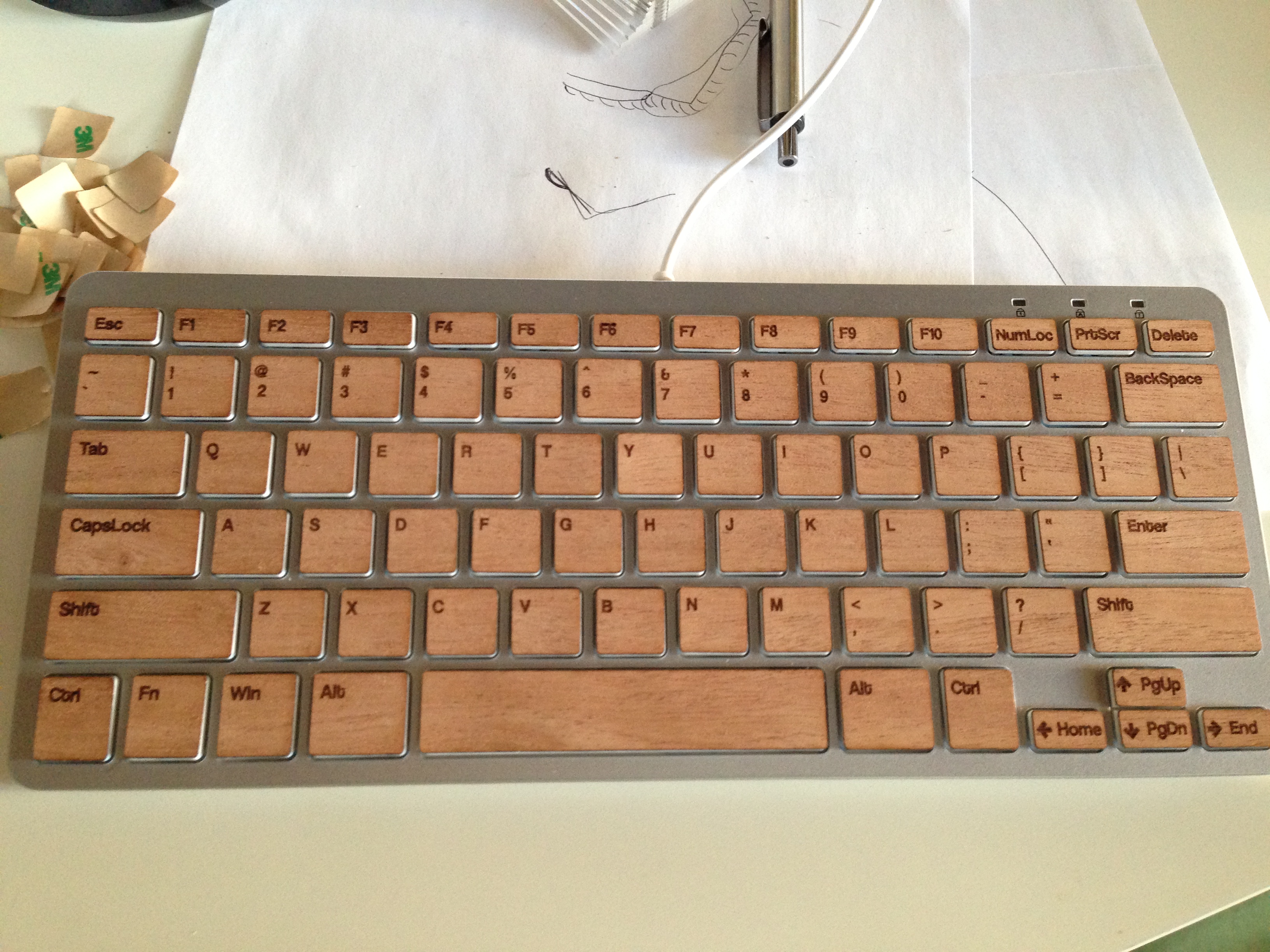
After uploading the dxf, the next step was simply to add in the text to the keys for etching. As this was quick, I kept fonts the same size and tried not to overcomplicate it. Once I had the text etched, I simply cut out the keys (without moving the stock) and pulled the letters off for application.
As I mentioned above, there are a few errors on this that need some quick fixes. The two main things are that I overestimated the kerf and didn’t sand and finish the veneer before cutting. Both of these can be addressed pretty quickly, though, and I should have an update in the next few days with a better looking revision.


Radius Gauge
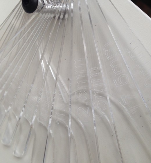
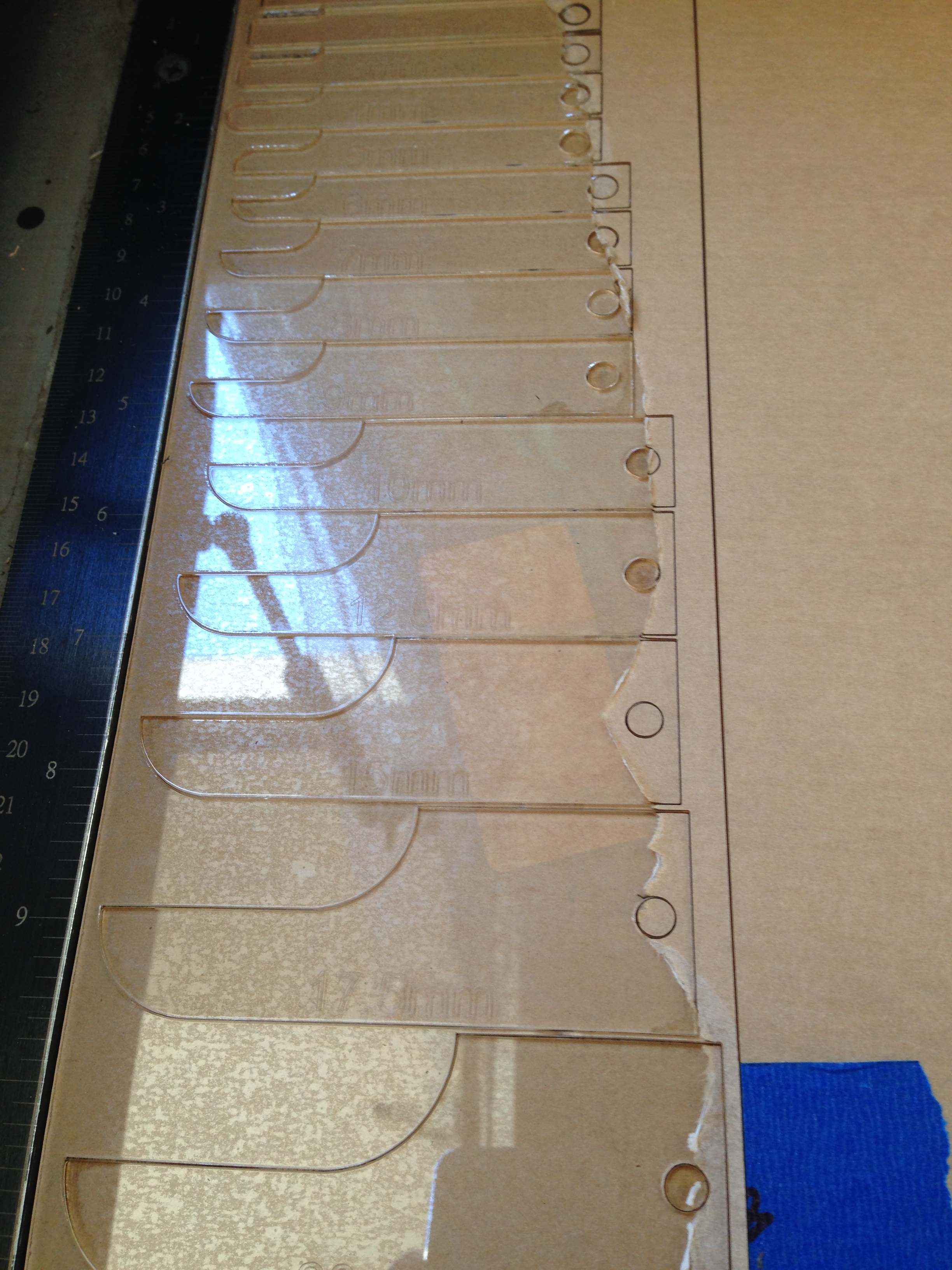
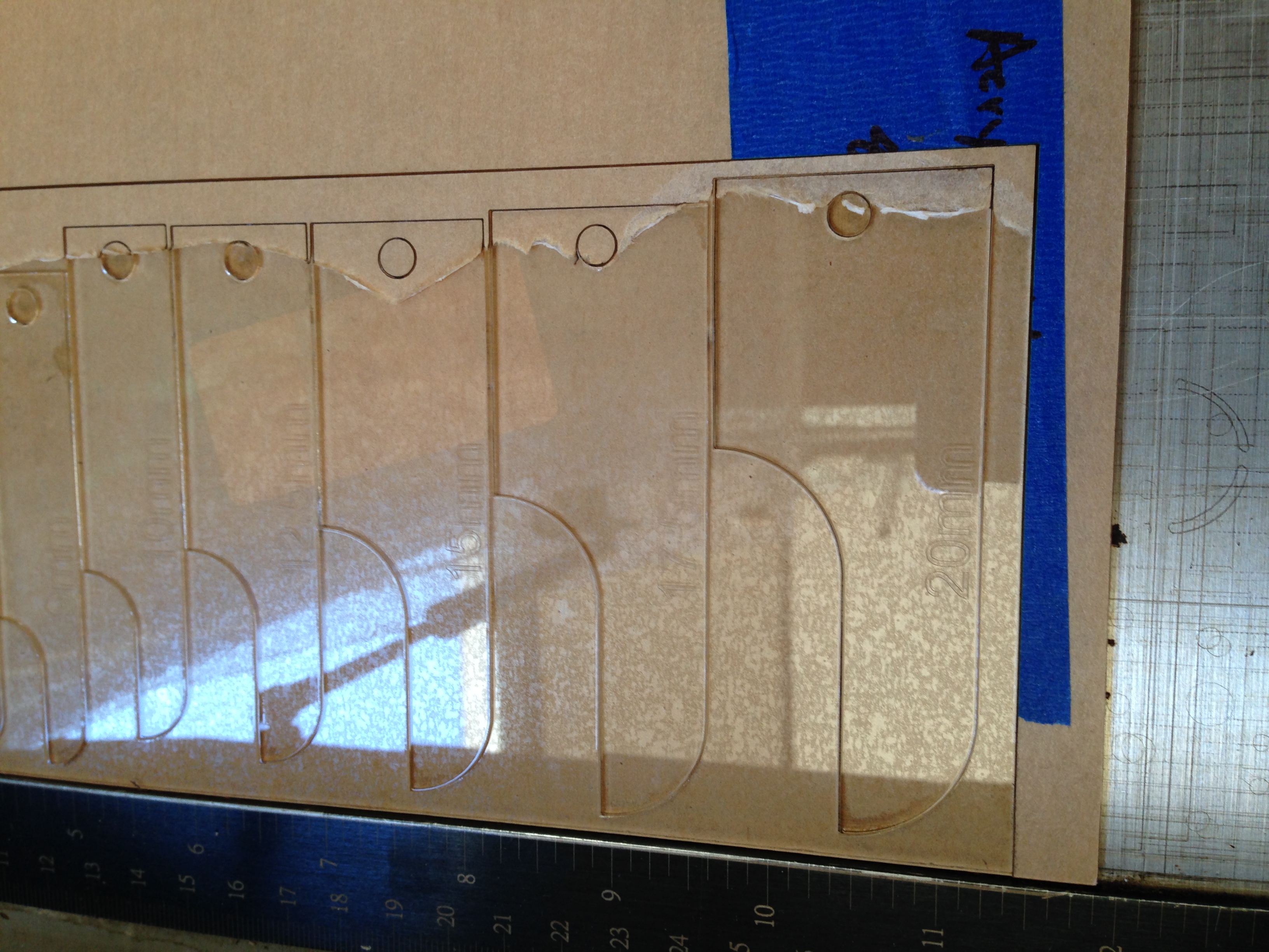
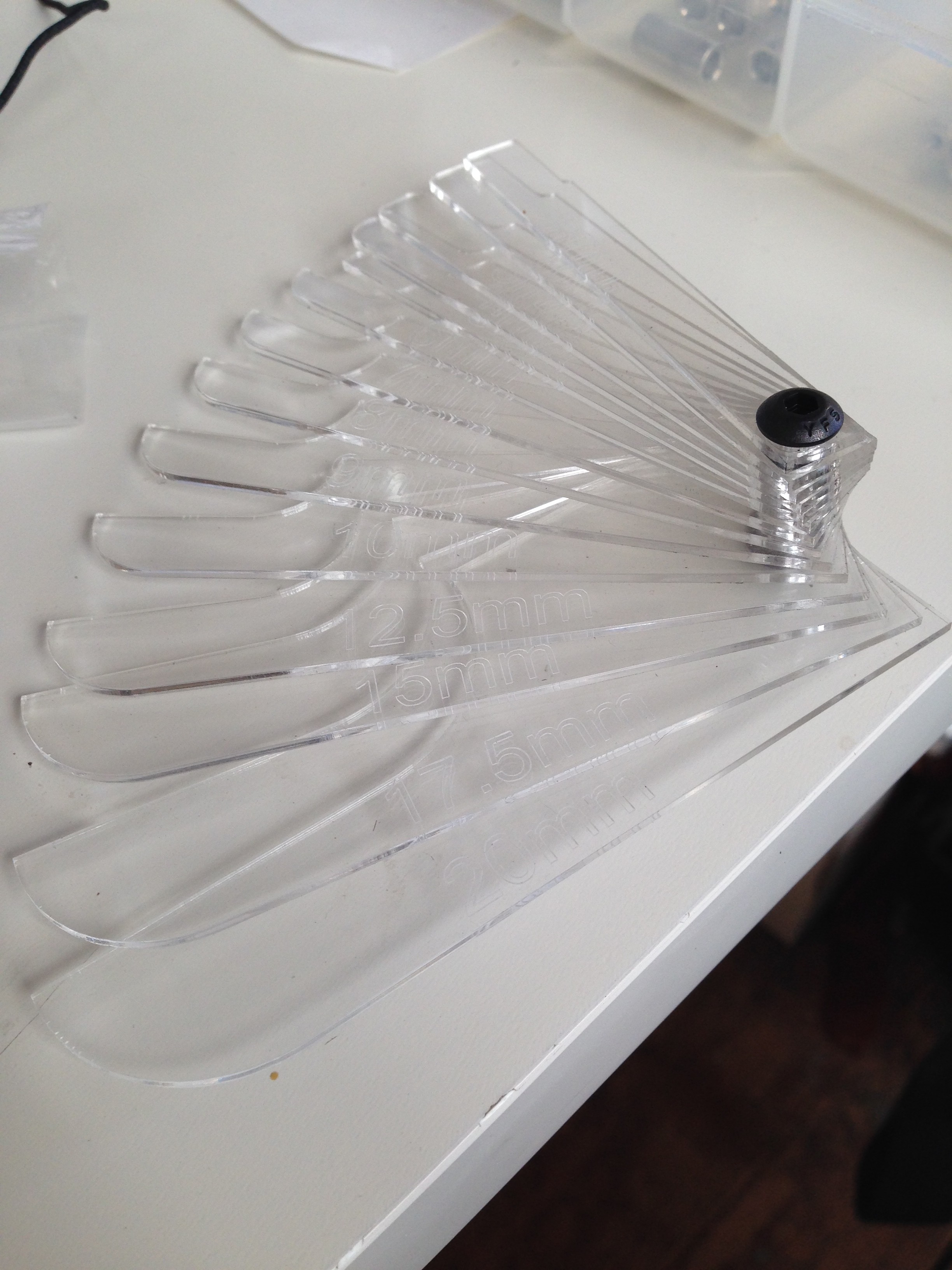
So, one of the tricky things you find with modeling physical parts is that its very difficult to accurately measure the curvature of a face or radius on a fillet. Often, a set of calipers will get most of the linear measurements accurately, but we’re stuck guessing or making up the radius of parts when modeling them in CAD. So I looked around at some samples of radius gauges on the market and decided to take a few minutes to make up one to have in the shop. The process for this is fairly straightforward, as I wanted to have a range of measurements along with the ability to check both the interior and exterior of models. Since I’ve been doing most modeling in metric measurements recently, it made sense to use a mm scale.
Modeling for this is straightforward in Solidworks. I started by putting together one of the largest sizes that I would need, and dimensioned it using relations based on a single radius measurement. This allows you to either set up a table for redefining that single measurement for the other sizes, or creating a bunch of new configurations based on the one dimension. This got a little tricky once you get down to the small sizes. As you don’t want the gauges to be too small to be usable, I ended up modifying the smallest 4 in order to keep the total width to 10mm.
I found a threaded standoff to use that could hold these together and allow the user to spin one out a single gauge for measurement. This was one we had around the shop, but it looks to be a 3/4″ 4-40 standoff very similar to McMaster P/N 91125A437. A couple button head screws for caps and some loctite should work for the rest. As for material, I went with some thin 1/16″ clear acrylic we had around the shop. I didn’t want to go too thick with the material, so it seemed like a good option.
A dxf of the cut pieces is availible here:[gview file=”http://motimindustries.com/wp-content/uploads/2013/10/radius-gauge.dxf” profile=”4″ save=”1″] Note that I haven’t made any adjustments for the kerf of the laser that I used to cut mine, as yours might be different. Adjust accordingly. Once I imported the dxf into Corel, I simply typed in the labels for each size and etched those along with the cut pieces.
Bridgeport CNC Retrofit
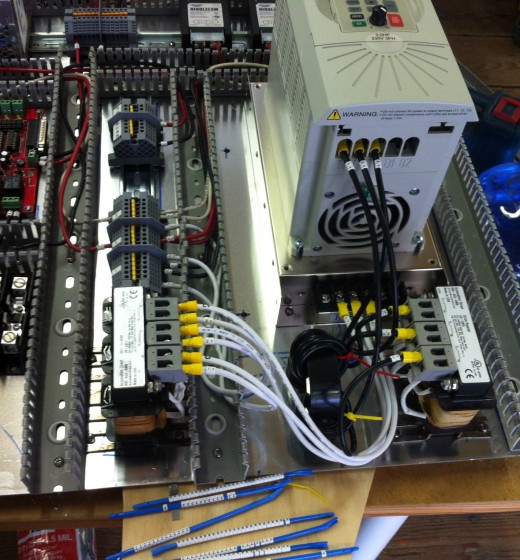
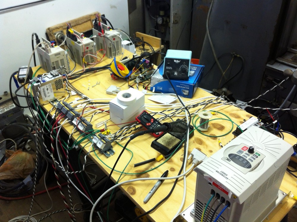
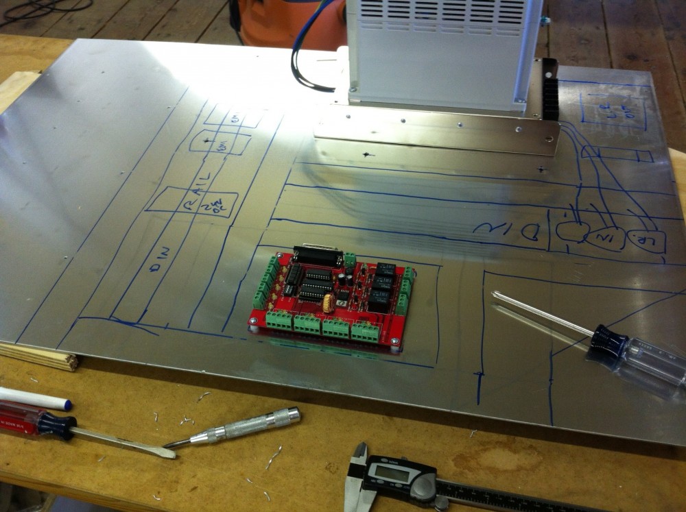
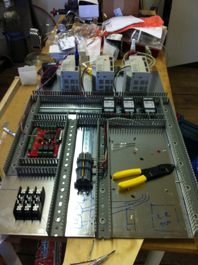
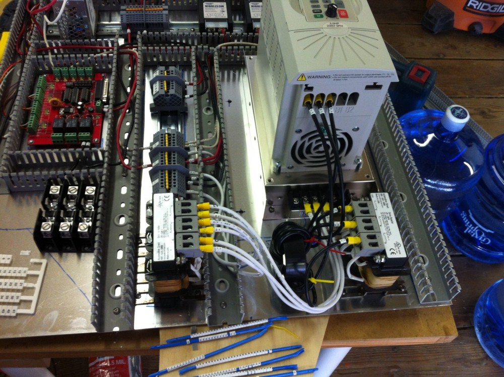
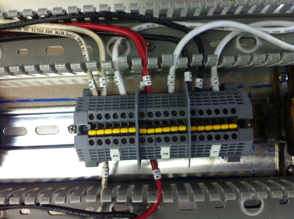
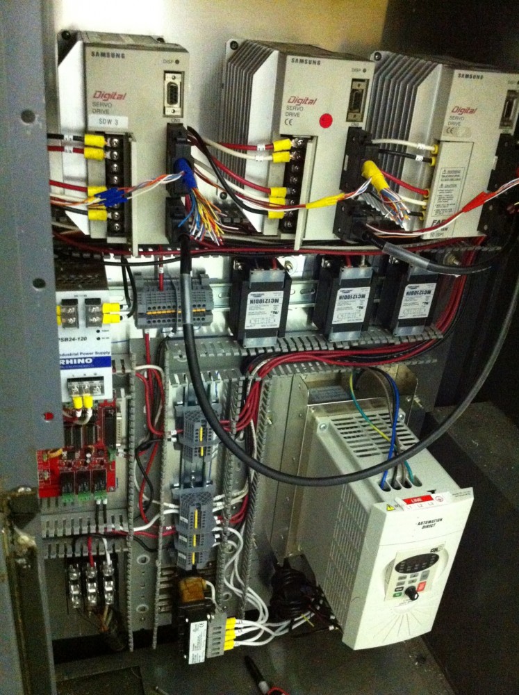
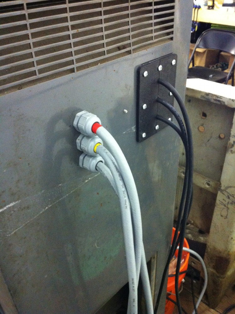
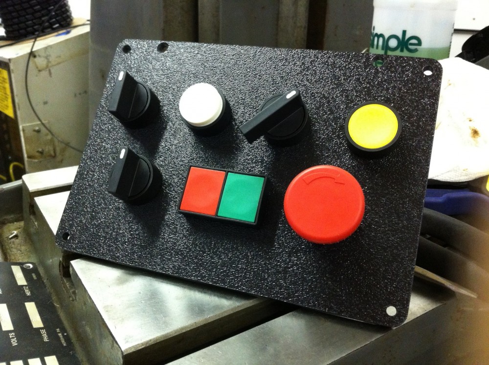
Our Bridgeport Series I Boss 7 CNC Mill came with the original control system, along with the infamous automatic tool changer (this has been regarded as one of the worst CNC tool changers ever made). The machine was in great condition mechanically, but having the original control system means it had servo motors driven by quite old electronics. It was the perfect candidate for a retrofit to newer, upgraded controls.
The first steps we took were in an effort to reduce size. In any shop, you can never seem to have enough space, and Motim is no exception to that rule. The tool changer had a very complex pneumatic and electronic control system, and the enclosure for all those controls was enormous. Research pointed out that the Boss 7’s tool changer controls were unreliable at best, and at worst, the tool changer would occasionally throw a tool holder up to 30 feet. As such, we decided to forgo the use of the tool changer in favor of changing tools manually. Removing the tool changer and its control enclosure cut the footprint of our mill in half.
On to the important part, our upgraded controls. We chose to use 2000W servo drives with 2048 count encoders. They supply plenty of power, and give us about 0.00005 inch resolution. For the spindle, we kept the original motor, and powered it with a 3 HP GS2 variable frequency drive. It is all currently being controlled with Linux CNC.

Shop Equipment
In House Prototyping Tools:
Masterwood Project 316K CNC Router
Bridgeport Mill with upgraded CNC Control
Bits from Bytes BFB 3000 3d Printer
Pinnacle M-30 Laser Cutter/Engraver
Sherline 4000 Series Lathe
Sherline 5000 Series 3 Axis Mill with CNC control


