Radius Gauge
So, one of the tricky things you find with modeling physical parts is that its very difficult to accurately measure the curvature of a face or radius on a fillet. Often, a set of calipers will get most of the linear measurements accurately, but we’re stuck guessing or making up the radius of parts when modeling them in CAD. So I looked around at some samples of radius gauges on the market and decided to take a few minutes to make up one to have in the shop. The process for this is fairly straightforward, as I wanted to have a range of measurements along with the ability to check both the interior and exterior of models. Since I’ve been doing most modeling in metric measurements recently, it made sense to use a mm scale.
Modeling for this is straightforward in Solidworks. I started by putting together one of the largest sizes that I would need, and dimensioned it using relations based on a single radius measurement. This allows you to either set up a table for redefining that single measurement for the other sizes, or creating a bunch of new configurations based on the one dimension. This got a little tricky once you get down to the small sizes. As you don’t want the gauges to be too small to be usable, I ended up modifying the smallest 4 in order to keep the total width to 10mm.
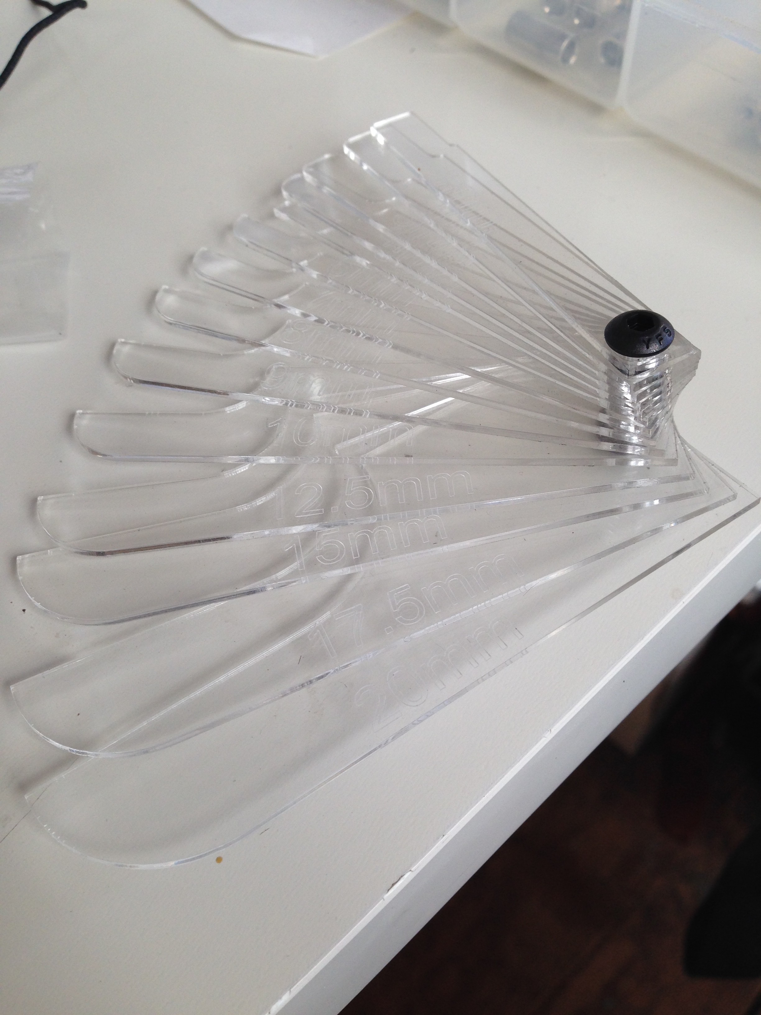
I found a threaded standoff to use that could hold these together and allow the user to spin one out a single gauge for measurement. This was one we had around the shop, but it looks to be a 3/4″ 4-40 standoff very similar to McMaster P/N 91125A437. A couple button head screws for caps and some loctite should work for the rest. As for material, I went with some thin 1/16″ clear acrylic we had around the shop. I didn’t want to go too thick with the material, so it seemed like a good option.
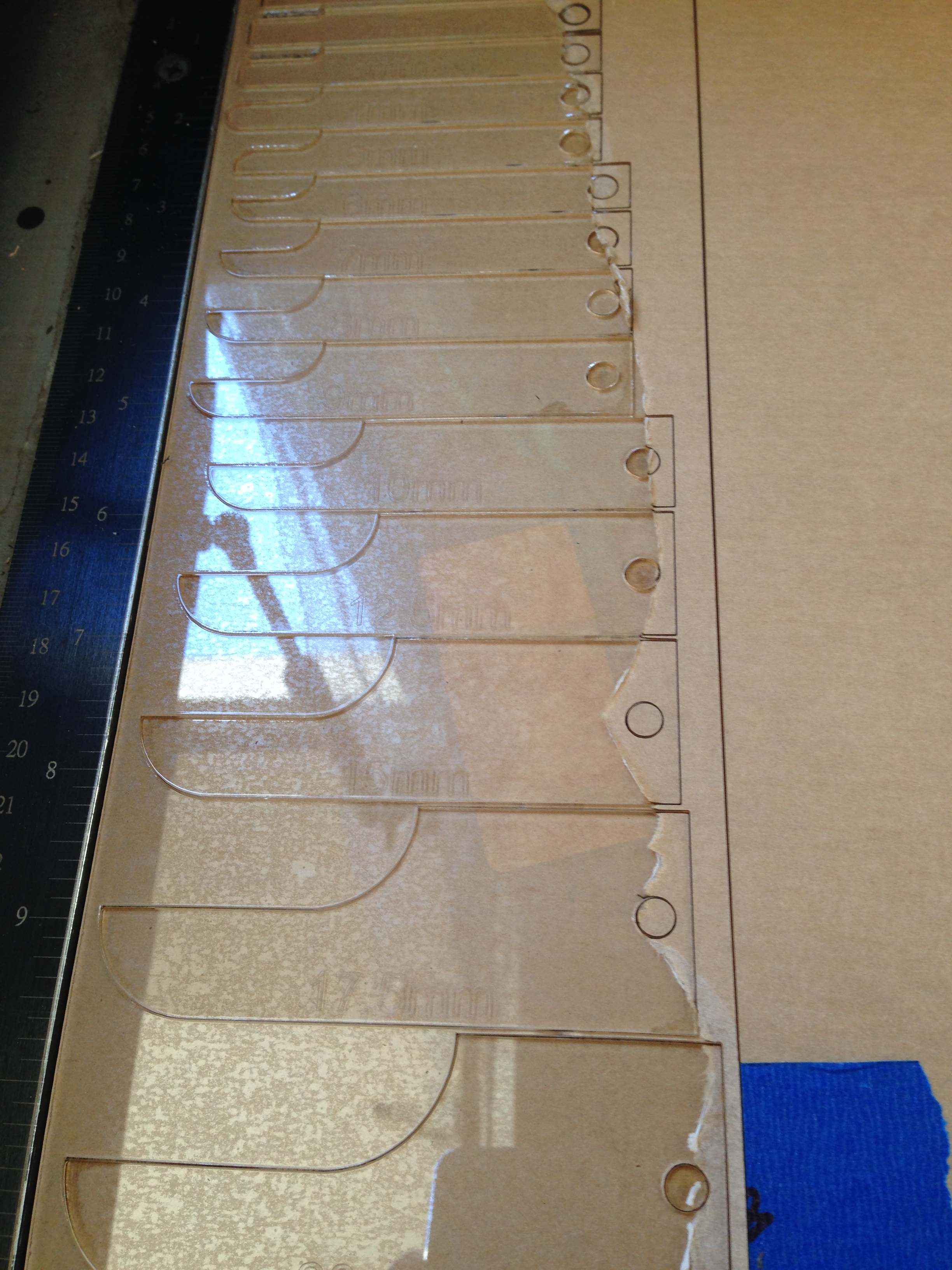
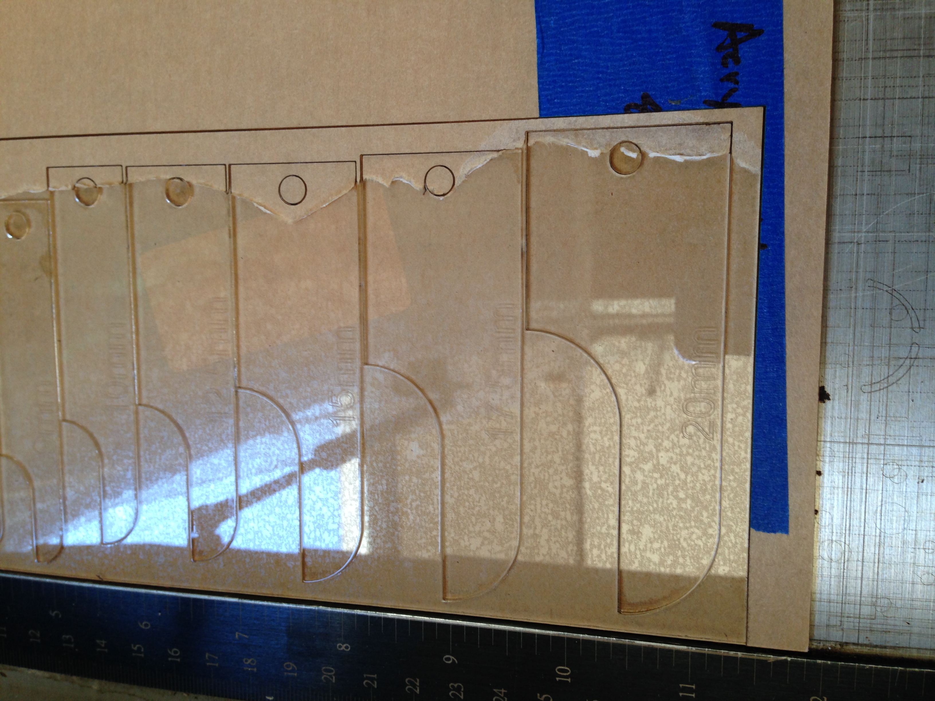
A dxf of the cut pieces is availible here:[gview file=”http://motimindustries.com/wp-content/uploads/2013/10/radius-gauge.dxf” profile=”4″ save=”1″] Note that I haven’t made any adjustments for the kerf of the laser that I used to cut mine, as yours might be different. Adjust accordingly. Once I imported the dxf into Corel, I simply typed in the labels for each size and etched those along with the cut pieces.